Table Of Content
41 (supersonics) are classical solutions in the airfoil theory and allow the determination of the lift coefficients on airfoils at small angles of attack. These thin airfoil approximations agree well with measurements of the lift-curve slope made on thin two-dimensional airfoils, as shown in the figure below. The linearized supersonic theory also has good validity when extended to three dimensions, such as predicting the lift-curve slope of a finite wing with a higher aspect ratio. The pressure distributions around airfoil sections are non-uniform, with higher and lower pressure regions relative to ambient pressure, with typical variations shown in the figure below.
The Airfoil Adventures of Harry Riblett
It is generally impossible to find the drag this way, however, at least using measurements, and usually, a momentum deficiency approach is used. By definition, the aerodynamic center is a point where the moment is constant and independent of the angle of attack. The procedure for finding the aerodynamic center, like that for the center of pressure, requires values of the lift and moment coefficient about any other point, say a distance from the leading edge. Where is the chord of the wing section or the airfoil, which is the distance from its leading edge to its trailing edge.
Other NACA Airfoils
Similar to the panel code, this develops an NxN algebraic and linear system that is solveable. The various upper and lower surface points can be exported to a data file, as shown in the figure below, and the airfoil’s final shape is then obtained by connecting the points. Generally, more points will be needed in the nose region of the airfoil because of the section’s higher curvature.
Dynamic Pressure
The force component on the surface in a direction parallel to the relative wind direction is called the drag. Moments can also be produced on the lifting surface about each of the longitudinal, lateral, and vertical axes. A lift and drag curve obtained in wind tunnel testing is shown on the right.
A comprehensive review of innovative wind turbine airfoil and blade designs: Toward enhanced efficiency and ... - ScienceDirect.com
A comprehensive review of innovative wind turbine airfoil and blade designs: Toward enhanced efficiency and ....
Posted: Fri, 10 Nov 2023 13:31:59 GMT [source]
Therefore, to calculate the location of the aerodynamic center, the slope of the lift curve (in the linear range) and the slope of the moment curve (also in the linear range) are needed. Remember that the linear range corresponds to the conditions where the flow would be fully attached to the airfoil surface. This process is performed by finding the slopes of the best straight line fit to the values of versus and then versus in the linear range (attached flow). Pitching moments about the 1/4-chord are usually relatively low on most airfoils, but for a significantly cambered airfoil, as in the case shown, the moments will be non-zero.
Notice, however, that there is also a decrease in the stall angle of attack with flaps. The National Advisory Committee for Aeronautics, or the NACA, which is always pronounced as “N-A-C-A” and never “NACA,” conducted the most comprehensive and systematic study of the effect of airfoil shape on aerodynamic characteristics. Existing cambered airfoils, such as the Clark-Y and Gottingen sections, were known from the earliest wind tunnel experiments to have good aerodynamic characteristics. Therefore, the NACA used these airfoils as a basis; these two airfoils had geometrically similar profiles when the camber was removed, and the airfoils were reduced to the same thickness-to-chord ratio. A polynomial curve fit defined the resulting thickness shape, which became fundamental to many of the subsequent NACA airfoil families, i.e., what has become known as the classic NACA 00-series symmetric airfoils.
Effects of Mach Number

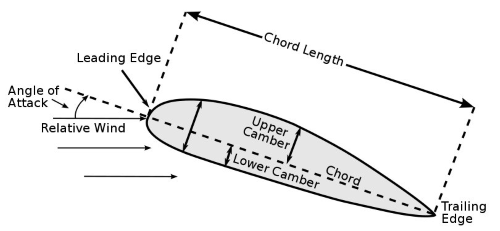
A typical airfoil and its properties are shown in Figure 2,and are also described below. Notice the use of lower-case subscripts on all coefficients (e.g., , not and , not ) when applied to a “2-dimensional” airfoil section. When applied to a finite span wing, capital letter subscripts are used, as discussed later; this standard notation distinguishes the finite-span aerodynamic coefficients from the two-dimensional ones. Notice that dynamic pressure depends on the squared value of the flow speed. It can be easily confirmed that dynamic pressure has units of pressure, i.e., force per unit area so that it will be expressed in base units of Nm (Pa) in SI or lb ft in USC. The third aircraft that we’ll use to round off our airfoil comparison is the General Dynamics F-16 Fighting Falcon.
Straight-and-level flight:
You can under camber just the outer section of a wing to increase stability. If the critical condition (either regulatory, or for performance reasons) is in a landing configuration with high lift devices deployed, then the CLMAX of the bare airfoil is of secondary importance. What counts is the lift characteristics of the wing with the high-lift system deployed.
History of Airfoils
Viscosity can be described as the "thickness," or, for a moving fluid, theinternal friction of the fluid. A parameter of viscosity is the coefficient of viscosity, which is equal to theshear stress on a fluid layer over the speed gradient within the layer. Since the velocity of the fluid below the wing is slower than the velocity of the fluidabove the wing, to satisfy Equation 3, the pressure below the wing must be higher than thepressure above the wing. One method is with the Bernoulli Equation, which showsthat because the velocity of the fluid below the wing is lower than the velocity of thefluid above the wing, the pressure below the wing is higher than the pressure above thewing. Where is the boundary layer shear stress, which is proportional to the velocity gradient at the surface.
Unlike subsonic airfoils, supersonic airfoils produce strong shock waves. These shock waves create significant pressure changes, affecting the airflow and aerodynamic performance of the airfoil. As the Reynolds number decreases below one million () and the effects of viscosity begin to manifest more significantly compared to inertia effects in the flow, the lift and drag characteristics change more profoundly. The data in the figure below shows the profound effects of operating airfoils at lower Reynolds numbers, which in this case range from as low as 20,000 to 3,000,000 (three million). It can also be inferred from the previous discussion that surface roughness encourages turbulent mixing, destroying the laminar boundary layer in short order. The resulting increase in skin friction drag makes the airfoil perform comparably (or sometimes worse) than a conventional airfoil.
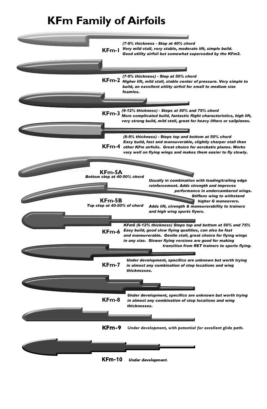
They’re simple to manufacture, draggy (which is sometimes good for creating a stable flight experience) but are often sensitive to changes in airspeed which makes them difficult to trim. The field of fluid mechanics is populated with a lot of very clever people who really know what they’re doing. As amateurs in the field of RC airplanes, it’s sometimes difficult to get our heads around subjects such as airfoil types and which is the best for a given aircraft.


No comments:
Post a Comment